NTRIP serviceinternetROVER
You need 1 module
The NTRIP client is built in. Enter your caster details in the web panel and the rover receives corrections over Wi-Fi.
Configure in a web browser over Wi-Fi. Get corrections from an NTRIP service or your own base. Read positions as standard NMEA over UART. Add the autopilot and your robot drives from waypoint to waypoint.
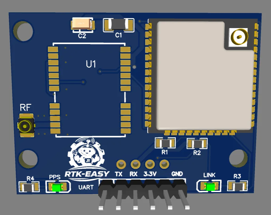
An RTK rover needs correction data to reach centimetre accuracy. RTK-EASY takes it from the internet or from your own base station.
The NTRIP client is built in. Enter your caster details in the web panel and the rover receives corrections over Wi-Fi.
Switch one board to BASE mode and it becomes your own RTK base station, generating corrections for your rovers. No dependence on a public service.
Connect the rover to an ESP32, Arduino, computer or any controller and read:
Attach the GNSS antenna and power the module. Mount the antenna with a clear view of the sky.
Join the module over Wi-Fi from a phone or laptop. Choose BASE or ROVER, set Wi-Fi and the correction source.
Watch status and RTK fix in the browser, or read NMEA from the UART output in your own code.
From RTK basics and first setup to a robot driving RTK waypoints on its own.
Both modules come in two GNSS series, L1/L2 and L1/L5. Pick the series under each product to see its board.
A ready-made module for precise RTK positioning. Use it as a rover that knows its exact location, or switch it to base mode and run your own RTK base station.
For robots and other autonomous platforms. It knows where the robot is, works out where it has to go next, and sends drive commands to the wheel controllers. No separate computer is needed to turn RTK coordinates into motion.
A plain rover knows where it is. The Rover/Autopilot also knows where it needs to go, and tells the wheel controllers how to get there.
The autopilot compares its RTK position with the next waypoint, calculates the heading and speed, and sends wheel commands until it arrives.
| L[50] R[-50] | Both wheels forward |
| L[30] R[60] | Turning |
| L[-40] R[40] | Reversing |
| [0] | Stop |
The autopilot does not drive high-current motors directly. It decides where and how the robot moves. The wheel controllers handle the motors.
An ESP32 server board that plans routes for the autopilot, or turns any RTK-EASY wheel controller into a web-controlled robot without writing a line of code.
Draw the perimeter and any obstacles in the browser, set the coverage angle and row spacing, and click Plan route — the server board computes the full coverage path and lets you preview it with the built-in rover simulation before driving anywhere.
The last plot you save becomes the live route. On its next run, the RTK Rover/Autopilot reads that saved route straight from the server over Wi-Fi — nothing to re-upload to the rover.
It also works the other way: transfer a plot recorded by the autopilot back to the server, generate a route from it there, then drive that generated route once it's back on the rover.
Upload the server firmware and the board becomes a route planning server on your network. Plan the waypoints in the browser; the RTK Rover/Autopilot receives them from the server over Wi-Fi.
Don't want to program your own ESP32? Connect this board to a wheel controller and you have a robot you drive from a web page.
Both reach centimetre-level accuracy with RTK corrections. The difference is which satellite signals they use.
The all-round choice for varied conditions.
Choose L1/L2 if you don't yet know where the device will be used.
A strong choice for open areas with a clear sky.
L5 is a newer GNSS signal, but fewer satellites broadcast it than the older signals. In harder environments L1/L2 is usually the more versatile choice.
Neither series can work miracles here. A GNSS receiver needs the widest possible view of the sky. Under dense trees, next to tall buildings, under a roof or between buildings, RTK performance can drop, or an RTK FIX may not be reached at all.
A robot has to know where it is and where to go. Something also has to turn the wheels. RTK-EASY supports two drive types with the same simple command interface.
For robots with ordinary brushed DC motors. More than a simple power stage: it monitors each motor and works to hold the set speed when the load changes. When the robot climbs a slope or drives into grass, it adds power so the wheel speed changes as little as possible.
For larger and more powerful robots with BLDC hub or wheel motors driven by ZS-X11H power stages. The board sends them speed and direction signals and reads the wheel Hall sensors.
Same autopilot, different drivetrains. A small robot can use brushed DC motors, the next project BLDC motors, with no changes to the autopilot logic.
Connect a standard ESP32 Dev board to any of our wheel controllers and upload the free, ready-made firmware. Your phone becomes the remote.
The ESP32 creates a Wi-Fi network and a web control page. Connect with your phone, open the browser and drive with the on-screen joystick. No app, no dedicated remote, no extra hardware. Try the joystick demo, or watch the real robot.
Wheel controller + ESP32 Dev + free firmware. Or skip the ESP32 setup: use the Route planner board, ready to connect.
Replace the ESP32 with an RTK Rover/Autopilot. The robot knows its exact position and drives the waypoints on its own.
Start with two motors, a wheel controller and an ESP32. Upload the firmware, connect the ESP32, and your robot is driving.
The ESP32 and the RTK Rover/Autopilot RX inputs are 3.3 V only. Connecting the 5 V controller TX directly can damage them.
In Wi-Fi mode the ESP32 draws current peaks of several hundred milliamps. Feed its 5V pin from a 5 V DC-DC regulator on the robot battery, or from a separate 5 V supply. Do not take 5 V from the wheel controller.
TX2 → RX needs no divider. Connect all grounds together.
Using the Route planner board instead of an ESP32 Dev? Its UART2 RX accepts 5 V, so connect the controller TX directly.
A professional RTK receiver is usually a finished measuring instrument. RTK-EASY is an RTK module designed to be easy to understand, connect, configure and use in your own project.
| Typical survey receiver | RTK-EASY | |
|---|---|---|
| Designed as | A finished measuring tool | A module you build into your own device |
| Configuration | Vendor software or GNSS commands, often via a PC | Web panel in any browser over Wi-Fi |
| Position output | Tied to the vendor's app or controller | Standard NMEA over UART |
| Corrections | NTRIP or a separate base | NTRIP built in, or your own RTK-EASY base |
| Robot navigation | Needs an extra computer and software | Built-in waypoint autopilot with wheel control output |
Less complex configuration. More freedom to build.
Answer four questions and get a recommended set of modules. Copy the list and send it with your enquiry.
Only if you have no access to an NTRIP correction service, or you prefer not to depend on one. With NTRIP, one rover is enough. Without it, use two modules: one in BASE mode and one rover.
With RTK corrections and a good view of the sky, both series can reach centimetre-level accuracy once the rover has an RTK FIX. Trees, buildings and roofs reduce performance.
The rover sends standard NMEA sentences over UART. Any ESP32, Arduino or computer with a serial port can parse latitude, longitude, altitude and fix status (GPS, FLOAT, FIX).
No. All settings, including BASE or ROVER mode, Wi-Fi and the correction source, are made in the web panel from a phone or computer.
If you are unsure, choose L1/L2. It is the more versatile option across varied conditions. L1/L5 is a good fit for open terrain with a clear sky.
3.3 V. Never apply 5 V to the UART pins. When connecting a 5 V motor controller TX line, use the resistor divider shown in the wiring section.
Yes, if they accept the autopilot's simple UART wheel commands. The RTK-EASY DC and BLDC controllers support them out of the box and add speed regulation and battery monitoring.
No. The Route planner board works as a ready-made Wi-Fi robot controller. Connect it to a wheel controller and drive from the web page. Its UART2 RX accepts the controller's 5 V signal directly.
Yes. Upload the ready-made firmware to a standard ESP32 Dev board, connect it to an RTK-EASY wheel controller and drive from your phone.
Modules are made to order. Send us your recommended set from the kit builder, or describe what you are building, and we will confirm the configuration and lead time.